

Trick or treat: a cobra masquerading as a cable, waiting to strike the unwary.
I never had any intention of wiring my tiny house myself. I knew I could learn it if I had to but when you’re building a house on your own there are some tasks you need to let go of to save your sanity. Since electricity scares the bejeezus out of me, it was a no-brainer to hire that one out. Then two things happened: I got an estimate for what it would cost (yikes!) and I met Todd Clay, the owner of Gorge Electric, who took an interest in my project and agreed to mentor me if I wanted to take it on myself. So that is how I came to be a reluctant electrician.
I am way behind on progress updates, but I realized that the primary purpose of this blog is to share the lessons I’ve learned while building Naj Haus and since the wiring experience was a pretty big deal, it’s worth backing up and going over it in more detail. Jumping into the world of electrical wiring as a complete novice required learning entire new vocabulary, tool, and skill sets, and a mind-boggling array of materials and safety precautions. Fortunately I had Todd to guide me with all of his expert advice, but he’s a busy guy and we could only arrange periodic check-ins and inspections; the rest of the time I was on my own. While the internet is a wealth of information, it’s all so piecemeal it can be hard to see the forest for the trees. As I gradually wove my way through the morass, it began to make more sense. I thought I would present my experience as a case study so that others might not have to go through the same torturous process of figuring out how all the pieces fit together.
There are several caveats. This is not a step-by-step instruction manual but more of a framework to help you understand where you should focus your own research. I’ll point out tips and resources I used, but you may find better ones. Keep in mind I am not licensed and you shouldn’t take anything I say as correct. Code varies from location to location and from year to year so you really need to work with someone qualified. While tiny houses on wheels do not require permits and inspections, you definitely want to make sure your house is wired properly, both for your safety and that of others, and to help get insurance if you want it.
What I want to do is describe the process I went through, tailored to my situation, and point out how you can adapt it to your own. I also want to highlight some of ways that wiring a tiny house is slightly different than wiring a traditional house, and what safety precautions you need to be aware of besides the obvious ones talked about in the internet links. Even if you’re not doing the wiring yourself, knowing about some of these issues will help you work with your electrician. Finally, I’ve added lots of photos since there are never enough visuals when you’re trying to stumble your way through something you haven’t done before! They may or may not be pertinent to your situation but if I can help save you some headbanging and muffled swearing, then it’s all worth it.
Here are the topics I touch on in the rest of this post (my posts are getting so long they need a table of contents!):
- Lighting design: why this is important in a tiny house & the list of principles that guided me
- Developing a wiring plan: questions to research & some resources for finding answers
- Circuit diagramming: an iterative process best done with all fixtures in hand
- Installing a circuit breaker box: creating an insulated thermal break & hiring out subtasks
- Getting acquainted with the world of electrical device boxes & some installation approaches:
- What is a device box?
- Different types: Old work vs new work, plastic vs metal, attachment alternatives, special purpose
- Size matters: box fill capacity & why it’s particularly important in a tiny house
- Adjustable boxes
- Junction boxes
- Exterior device box installation
- Hanging light box installation
- Fan or saddle boxes
- Pancake box installation
- Exterior light box installation
- Tips for rough-in wiring: drilling through studs, running & anchoring cable, nail plates
- Tips for making up boxes prior to finishing walls and installing devices: stripping wires, crimping ground wires, wire nut capacity, tucking them in
- Next phase: wiring devices into boxes & attaching fixtures…a couple initial tips

Some sconces I got, hanging in a temporary spot.
Lighting design
The first step I did was to spend time thinking about lighting design. There’s a real art to this, as any interior decorator or theatrical lighting designer can tell you. From a purely functional perspective, lighting a tiny house is easy. The space is so small that you could throw in a couple light fixtures and immediately flood the place with more than enough light to do everything you need. The art part comes in as you work out what kind of ambiance you want and figure out how to create that. This involves things like the number, type and placement of light fixtures and the wattage, type and light temperature of bulbs. The intensity, direction and color of light can radically alter a space, especially one as small as a tiny house, and affect how you feel in that space. Spend a little time playing with different lighting and see what you respond to. This is part of designing viscerally and creating a space that feels comfortable to spend time in, despite it’s small size.
I realized there are certain lighting features and requirements that are very important to me to create the kind of ambiance I want in my tiny house. Coming up with a list of these greatly helped to guide me in finalizing my lighting plan and selecting my fixtures. Here are the guiding principles I came up with (your list might look completely different):
- I strongly dislike overhead lights, preferring instead lamps, task lights, and indirect-light sconces.
- I want to have multiple lighting alternatives in the house. Providing variety in lighting options can make a tiny house more visually interesting and give the illusion of a multitude of different spaces, rather than having just the same old one or two rooms constantly in view in the same way. Shadows and dark areas are just as important to consider as lit ones for creating this sense of different spaces (i.e., turning on various lamps or task lights at different times and in different combinations will create multiple unique pools of light and darkness and alter your experience of the space). Ideally I’d have every light on a dimmer for ultimate control and diversity.
- Warm light is extremely important to me and so fixture and bulb selection was governed by the type of light temperature emitted by the bulb or by having a light fixture and/or shade that warms the light.
- Somewhat in conflict with number 3, is a desire to primarily use LED bulbs for energy efficiency and low power usage. Fortunately the technology is getting better with offering warmer visible light bulbs. I’m also really sensitive to light flicker, which ruled out some types of lights and bulbs.
- I wanted the light fixtures themselves to be visually interesting, and more on the funky retro side than contemporary. While I went cheap on some of my fixtures, I was willing to splurge a little on others since in a tiny space, with little room for displaying art, the fixtures themselves should be little sculptures in my book. I ended up with an extremely eclectic variety of fixtures, which may or may not work together in a small space. An argument could be made for visual consistency, but I decided I preferred to be governed by whimsy and that it would somehow all just work since I was the one who had chosen everything. We shall see.
- I wanted some wall-mounted lights for practical space-saving purposes, but also wanted to have table lamps in a few places to make it feel more like a home and less like a rented RV. Where I do plan to have table lamps, I designed the built-in furniture in a way to hide both the cords and the outlets to reduce visual clutter.
- Similarly, with wall space at a premium, I wanted to keep the number of visible wall switches and outlets to a minimum. Several of my lights were selected because they have built-in switches or pull chains. Alternatively, you can get two, or even three, stacked switches in in the space of a normal switch plate if you want to conserve space and don’t mind smaller toggles. Also, despite having minimal gadgets, I wanted plenty of outlets in convenient places (that seems to be one of the biggest regrets I’ve heard from tiny housers). Wherever possible, I came up with ways to make them fairly unobtrusive like hiding them within built-ins.
- To Todd’s bemusement, I absolutely refused to have switches or outlets that have little LED lights in them like so many do these days. Surprisingly, those tiny green lights can really light up a small space, especially if they are all over. This can be great if you want a night light but can also ruin both your carefully planned lighting design and a good night’s sleep, if ensuring a naturally dark nest is important to you. (Unfortunately all of my smoke, CO and LP detectors have these lights, but there is always duct tape!)
So that is my list, which hopefully will spark some ideas for you and help you figure out what is important to you. There are probably more aspects to consider if you spend time researching lighting design. Or you can just go with your intuition like I did.

Getting it down on paper.
Developing a wiring plan
After I had thought through the type of ambiance I wanted in my tiny house and other design criteria, I started putting together a wiring plan. I had a three-prong approach:
- I did a crash course on general wiring principles (many hours surfing the web and watching endless youtube videos).
- I figured out what key questions specific to tiny houses I had to research to make final decisions on wiring my house.
- I went back to my framing plans and floor layout to start figuring out where everything was going to go.
Only after I had done all this did I start to think about the specific circuits (see next section). I’ve listed other links throughout the post but here are a couple that have overviews of the entire wiring process for background; otherwise, get surfing and find your own!
Resources:
- The series of electrical articles at DIYAdvice.com (read through them all)
- Shockingly Simple – Ryan Mitchell, TheTinyLife.com ($20 ebook)
Here is a brain dump of some of the decisions you’ll want to hone in on and research in more depth, in no particular order (not an exhaustive list by any means, but it will get you started):
- Where might you want a 3-way switch? Typically if you have a loft, you’ll want to be able to turn a light on and off from both the loft and downstairs. This will require a different type of wiring so you’ll need to plan it into your circuit diagram.
- You will likely have certain outlets that will need a dedicated circuit because they will have high power loads. For instance, an outlet on a kitchen counter that will be used by a toaster oven, microwave, or coffee maker; or an outlet for a hot water heater, oven, or washing machine. These will also likely require higher amperage circuit breakers and different gauge cables. If you haven’t already, this is a good time to calculate out the power demands of all the gadgets and appliances you intend to have in your tiny house. A Kill-O-Watt meter is handy to have if the wattage isn’t listed on the appliance. I discovered in Oregon (and maybe elsewhere) you can check these out from your county library – very cool!
- Similarly, you will also need to determine whether you want 30 amp or 50 amp service into your house (110V or 220V). This will depend on the amount of high-load appliances you plan to have and the ease with which you’d like to be able to connect to existing power sources as you move your house over time. In preparation for your circuit diagramming, research how much load can safely go on a 15 amp and a 20 amp fuse. This will help you determine how many circuits you will need and how many breakers in your box. (Note: I have a very low load set-up on a 30 amp service so am less familiar with the higher load requirements; you’re on your own if you’re going that route!)

A 30 amp, 125V power cord for a tiny house. Be sure to know how long a cord you will need (efficiency drops the longer it is) and that the type of plug is compatible with the receptacle you are plugging into. Also be sure to get a cord with a locking mechanism so it won’t slip out. Some cords have a pistol grip-style, right angled end so that the cord will drop straight down from where it attaches to your house.
- Understand the difference between GFCIs and AFCIs and where you will put each of them. (See FAQs on AFCIs by Leviton and GFCI and AFCI explained by Decker Home Services.)
- Going solar-powered is a whole subset of research in itself. If you are committed to being entirely off-grid, you can wire your house entirely 12V but you will need to adapt all of your appliances and gadgets to work on low voltage. This is the most efficient option. For most people, it makes more sense to wire your house traditionally (110V) and if you add solar capabilities, you also add an inverter to convert the voltage. There is some efficiency lost, but this is usually outweighed by the convenience of not having to adapt your existing gadgets. Note that unless you plan on having large panel and battery arrays, you will likely still need to modify your power usage and reduce your dependence on any power-intensive appliances. The nice thing is that if you go with the second option, you can add solar at any time. Knowing I could plug into the grid at my initial parking site, I opted to wait on adding solar until I really need it, at which point the technology will likely be better and cheaper.
- Think about what you want on the exterior of your house in terms of porch light, motion detectors, and outlets. I put one outlet near the roofline so I can put up string lights that I can control from a switch inside. I also put a 20 amp receptacle (on its own circuit) in the porch area since I may have an outdoor kitchen where I can plug in a hot plate. I can also use it for tool use outside.
- Don’t forget to factor in range hood fans and bathroom vents (very important from a moisture control standpoint!); any ceiling fans (need to use special electrical boxes/hangers for the added weight and motion stresses); any special wiring for music, internet or other media use; and whether your smoke, carbon monoxide, and liquid propane detectors will require outlets, be hardwired, or will depend on batteries. I’m sure there’s more I’m not thinking of at the moment!
- To some extent, try to think what you might want in the future that you can wire for now before you close in your walls, keeping in mind there’s only so much you can reasonably plan for in the present moment since you don’t know what your needs will be in the future. For awhile I thought I might want to put in the LUNOS2 heat exchange system, but was discouraged by the cost. I contemplated putting in the wiring for it so I could easily add it later if I needed it. In the end I decided not to since there were too many unknowns and the technology would probably change. However, I did put in a dedicated outlet under my sink area in case I ever decide to add plumbing and a hot water heater. It was a simple thing to do with the added bonus is that if in the interim I find myself needing a supplementary electrical heater, I know I can use that plug without overloading another circuit. Additionally, its helpful to leave room for a couple extra circuit breakers should you need them.
My spare 20 amp outlet on it’s own circuit, wondering if it will ever achieve its destiny of supplying a hot water heater…
As I grappled with the issues above, I started putting things down on paper. I updated my framing plan elevations with the actual as-built stud placements and then put tracing paper over them to try out locations of light fixtures, switches, outlets and other details. I also did this in floor plan mode. This was helpful for spotting potential issues, visualizing what it would look like and how accessible devices would be, and for my discussions with Todd regarding circuit planning.
I would say that my wiring requirements fell in the medium range in terms if complexity. My appliances and gadgets are very simple in terms of load requirements (note I don’t have plumbing or a typical bathroom in my house, which makes some things easier, at least in terms of wiring!):
- Under-the-counter refrigerator, 274 kw/year
- Single stove top burner (propane, no electricity required)
- Spare electric hot plate for the rare occasion I need a second burner, 1300W
- AirKing range hood light and fan with continuous low-flow options for better air quality, 73W at highest setting (side note: thus range hood is ideal for tiny houses with the exception that the low flow controls are not easily accessible)
- Toaster oven, 1400W
- Fireplace/heater (propane, no electricity required)
- Small back up electric heater, 400W
- Various low-wattage lights and detectors
- Laptop, low wattage
- Cell phone, low wattage
My desire to have lots of control over my lighting options and to have lots of hidden receptacles added somewhat to the wiring complexity.
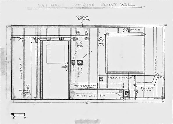
As-built framing plans with an overlay of potential fixture locations. This helped me visualize where electrical boxes could be most easily placed on studs for lights, switches and outlets.

Floor plan views can help you think through how many circuits you will need and the amperage loads of each. Using colored pens for each proposed circuit is very helpful.
Circuit diagramming
Once you have thought through all your conceptual design ideas and figured out your power needs, it’s time to start working out your circuit diagrams. This is where the rubber meets the road in terms of actual execution. There are many different ways you can plan out your circuits. For instance, it might make sense to have your circuits correspond to locations within your house (e.g., loft, kitchen, left side, right side, etc.) so that you know intuitively what is on a particular circuit if things go south. Or you might want to plan the circuits out based on functions they are serving (e.g., lights and low-load outlets might all go on one or two circuits despite where they are located in the house). Likely it will evolve into a combined approach, with certain circuits dedicated to particular appliances.
First and foremost, figure out a good circuit layout so you won’t overload any one circuit. Secondly, look at it from a wiring perspective and try to come up with the most efficient way to run the wires and connect the device boxes. You don’t want to have too many cables going through the same hole in a stud; how many depends on local code, the gauge of the wires, and how much load you anticipate running along the wires (i.e., how hot they will get). You will also need to understand how the devices and fixtures will actually be wired. Understand middle-of-run and end-of-run device wiring and how to wire 3- or 4-way switches if you have them, and any master/slave dimmer situations you might have. Know what gauge wire cables you will need for different appliances. Will you need low voltage wire and a transformer anywhere? Will you be using conduit? Do you understand the concept of circuits: how the hot, neutral, and ground wires connect to create a safe, complete loop? Since the electrical code is meant for traditional houses, you will need to decide how much you want to comply in terms of number, spacing, location and height of switches and receptacles. It’s a good place to start but might not make sense in your amount of space. As long as you understand about not overloading circuits, you should be okay.
Resources:
Most unfortunately, the series of videos I used the most for understanding how to design and wire circuits, complete with very clear animations and a Mr. Rogers-kind of narration, was pulled due to a copyright infringement claim. If you need to take a break and clear your head, you can watch this and listen to a similar sounding narrator:
Here are some other links I found helpful, but you’ll probably have to do some more research:

I went through several iterations of diagrams as I became more conversant in how many devices can be connected, box fill capacities, etc. Todd was great in pointing out elegant solutions for streamlining the wiring. Use both wall elevations and circuit diagrams. The wall elevations help you see what you will encounter in reality and the circuit diagrams help you spot places you might have too many wires coming into a box, exceeding capacity and thus where you might need either bigger boxes or junction boxes (see below).
For Naj Haus, I ended up with 30 amp service into the house (10 gauge wire from the inlet to the breaker box) with five circuits on AFCI breakers:
- 20 amp circuit for a dedicated exterior GFCI outlet that I may use when I want to cook outside (hot plate) or to plug tools into.
- 20 amp circuit for a dedicated interior GFCI outlet under the sink for a future hot water heater or just as an extra plug for heavier load items.
- 20 amp circuit for a kitchen counter GFCI outlet and the compact refrigerator (I may regret not having these on separate circuits but I was assured it would be fine. If not, I can plug the fridge into the spare outlet nearby).
- 15 amp circuit for half the house lights and receptacles and the range hood (all very low load)
- 15 amp circuit for the other half of the house lights and receptacles (also low low load).
The two 15 amp circuits don’t correspond to particular parts of the house but evolved as I figured out the most efficient way of wiring them. I ended up putting in two junction boxes so I wouldn’t have to add additional circuits (see below). I used 14 gauge wire for the 15 amp circuits and 12 gauge wire for the 20 amp circuits. Know what the difference is between 14/2 wire and 14/3 wire and where you would use each. Be sure to get cable with ground wires in it.
While technically you don’t need to have all your light fixtures, switches, outlets, and appliances on hand at the rough-in stage, I highly recommend it. There were many times I needed to know if light bases and devices would fit with selected device boxes, where to locate wires precisely (particularly for the range hood), and if there are any special wiring considerations. You may need to put in special framing for your range and bathroom vents.
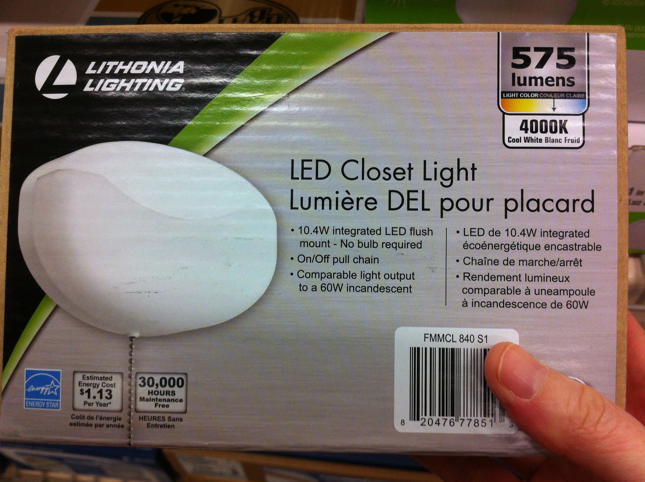
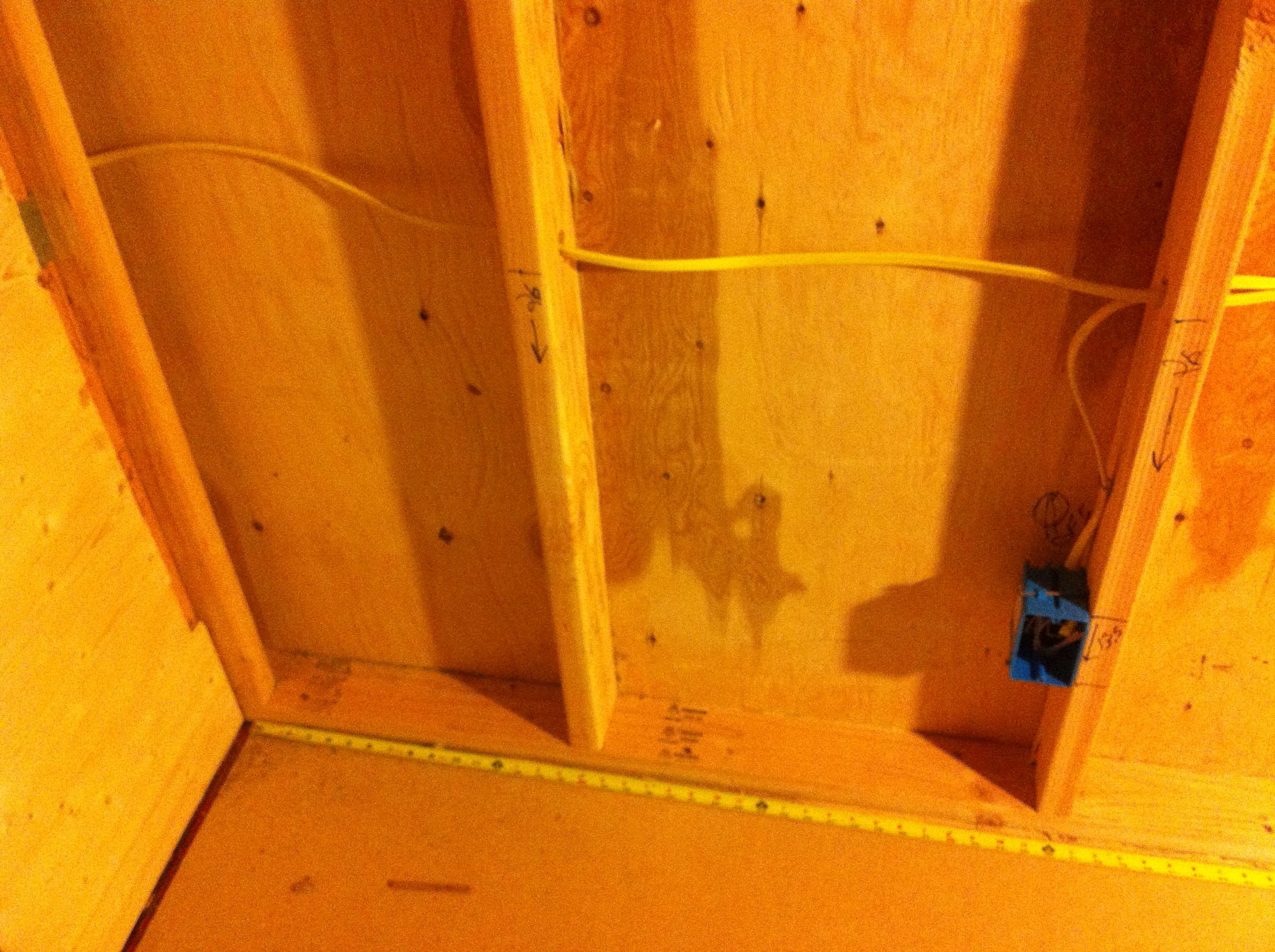
This was the closet light I ended up with since it was very efficient, small size, did not require a separate switch, and can be mounted in various ways. However, it was challenging knowing precisely where to have the wire come out of the wall since the closet hasn’t been built yet!

I admit it was a little obsessive but I made a diagram on a post-it for every device and fixture. It was really helpful for learning about wiring end-run and middle-run devices and working out trickier situations. I appreciated these little guys when I was making up my boxes (below).
As you work through your circuit diagramming, you may find that you need to give up on some of your design requirements for ease of installation. For instance, since I wanted minimal switches, I gave up on being able to dim a few of my lights or found ones with built-in dimmers. I also had this fabulous plan to put an LED tape light along the peak of my roof, hidden by a suspended piece if trim so that indirect light spilled out each side of the peak. I was going to control it by a 3-way switch on a master/slave dimmer upstairs and downstairs. I thought it would create amazing ambiance. I went so far as to wire in the low voltage wire and transformer before testing it and deciding I hated it! I was very happy to spare myself all the complex wiring and instead bought a cool retro loft light. Lesson: simple is generally better.

It looks kind of good here but wasn’t what I wanted when I tested it out.
Installing a circuit breaker box

The spoils of my first trip to the electrical supply store, one of many. Tip: some of the stores, like Platt Electric that cater to professional electricians, only sell cable and other supplies in large amounts (like 250′ rolls). This can be great at the beginning but if you run short and just need another 10-15′, places like Home Depot sell in smaller quantities. My local hardware store even sells cable by the foot.
The majority of tiny houses are constructed with 2×4 studs rather than the more standard 2x6s used in traditional construction in order to reduce weight and increase interior space. This can present some challenges when it comes time to wire your tiny house. Since most electrical supplies are made for traditional construction, standard breaker boxes and device boxes (for switches and outlets) will be up against the sheathing when installed. Since there isn’t room for insulation between the boxes and the wall, cold air can easily transfer into the house. While this can be a bit of an energy efficiency hit, a bigger concern is that warm moist air on the interior can potentially condense on the inside of the box and cause problems, particularly if you have moisture control issues due to poorly vented kitchens and bathrooms. If at all possible, it’s good to create even a small thermal break between the sheathing and the box by separating them slightly and filling the gap with insulation. It may not be a significant issue, particularly in my situation, but I decided to be safe than sorry.
Below you can see how I installed my breaker box. First I taped a piece of rigid foam board insulation to the interior sheathing. Then I added some framing to secure the box and screwed in the box to the framing, tightly sandwiching the rigid foam board. This caused the breaker box to extend out a bit from my finished paneling (see last photo), but I will trim out around it to make it less apparent.
[Tip: This is a good time to point out that doing your own wiring isn’t an all-or-nothing undertaking. While I did about 90% of it, I didn’t feel comfortable wiring the breaker box itself or installing a new circuit and exterior outlet on the backside of the barn where I am tapping into the main power panel. I happily hired one of Todd’s electricians to do this work. Cesar also installed the power inlet on the tiny house.]
Note: For all the photo galleries below, you can click on one and see a slideshow with larger pictures and captions.


Getting acquainted with the world of electrical device boxes & some installation approaches
The bulk of the rough-in wiring involves installing device boxes and then running cable to connect them. While some boxes are specialized for fans or hanging lights, the majority are generically used for either switches and/or outlets (receptacles). I was completely overwhelmed at first by the endless sizes and choices out there. Fortunately I’m going to lay it all out for you so you can be a little more suave at the electrical store than I was.
First thing to be aware of is that boxes are broken down into old work and new work. Old work boxes are for when you’re adding a box to an finished house, having to break through already-installed wall board. Old work boxes tend to have little wings and flaps to help secure them in the wall since you may not have access to nail into a stud. For the most part you can ignore old work boxes, though you might need them when you are installing exterior boxes through your siding (see below).
New work boxes are often, but not always, blue plastic (see the Carlon catalog for lots of helpful information). The benefit to plastic boxes versus metal ones is that you don’t need to ground them and they often have built-in cable clamps that don’t take up much space. But you may need to use metal boxes in certain cases. If you do, be absolutely sure you understand how to ground them properly so you don’t accidentally get electrocuted! New work boxes also vary in how they attach to framing (see below).
Device boxes can also be one-gang (or single-pole) or larger. One-gang boxes hold one device like a light switch or an outlet, though, as mentioned above, you can get switch devices that have two or three switches stacked on a single pole, or a switch and a single outlet stacked. Two-gang (or quad) boxes hold two poles for side-by-side switches or outlets, and you can get larger boxes for additional poles if you need them.
While one-gang boxes are roughly the same width and height, they vary significantly in terms of depth. This gets into two extremely important concepts that I haven’t seen discussed much in the tiny house blogs: thermal bridging and box fill capacity.
First let’s look at the differences in depth on different one-gang boxes:

A random selection of one-gang boxes that attach in different ways. Note the similarity in terms of height and width of the opening. The box in the upper right is called a pocket box. The flap on the outer right side folds back over the middle third and is slightly recessed, leaving the standard one-gang box opening on the left third of the box. This will be more clear below.
Now look at some of the same boxes in terms of how deep they extend into a wall:

The black box on the far right is about 3.5″ deep, the same as a 2×4 stud cavity. In contrast, see how shallow the pocket box is (second from the left), 1.25″ deep.

Here you can see the depth differences of the pocket box and the standard-depth black box in a 2×4 wall. You can also kind of see how the pocket box flap closes over on itself.
In traditional 2×6 framing, the black box above would still have a couple of inches between its back and the sheathing for insulation to create a thermal break, similar to what we discussed above with the breaker box. However, if you’re working in 2×4 framing, you won’t get that thermal break if you used device boxes like the black one since you won’t have any room for insulation behind it. This potentially could cause problems with heat loss and condensation.
So easy, just use pocket boxes everywhere, right? Unfortunately it is not that simple! Despite the clever design of the pocket to the side of the opening for housing wires, the pocket box still has less volume to hold wires and devices and clamps and wiring nuts than the black box. If you don’t have many of these, the pocket box works perfectly. If you have a lot and try to cram them all into the small space in the pocket box, you are greatly increasing your chances of shorts, sparks, fire, and, worst case, electrocution. So how do you know how much can go into a particular box and still be safe? The powers-that-be have figured this all out, but you need to understand about box fill calculations and box fill capacity.
Box fill calculations – choosing the right size box
This is where you need to do some homework. Promise me that you won’t install any boxes until you fully understand the concept of box fill capacity and how to calculate it. Promise? Okay, below are some links to get you started. Basically devices, clamps, and conducting wires are assigned points and you add up how many you plan to have in a box and multiply it by a special number depending on the gauge of your wire. This gives you a total box fill amount you need to contain.
Each device box has a box fill capacity amount (volume) listed inside it. As long as your planned box fill amount doesn’t exceed that maximum capacity, you can safely use that size box. If does exceed it, then you have to choose a larger box (or find an alternate solution like adding a junction box hub into your circuit – see below).
Resources for understanding box fill calculations and volume capacity:
- “Sizing Junction Boxes” at Hometime.com
- Mike Holt’s 2014 NEC – Outlet Box Sizing video
- Carlon Zip Box Blue Switch and Outlet Box catalog, which includes box dimensions and volumes
What does this look like in the real world? I used pocket boxes everywhere I could, primarily at the end of runs and where I was using just a simple switch or outlet. (Keep in mind that while pocket boxes are good solutions in terms of being able to fit the most insulation behind them, they are a little trickier to tuck wires into them once the box is closed up and the wall board is installed over the pocket side.) In places where I had GFCI outlets, dimmer switches, or other devices that were more bulky than a standard switch or outlet, or where I had a larger number of cables coming into and out of a box, I would use a larger capacity box. Fortunately there are some device boxes that are between the pocket box and the black box in terms of depth. You just need to know to ask for them (see the middle boxes in the photo above). In these cases I was still able to get a little insulation between the back and the sheathing to give me a bit of a thermal break. In a couple places, I wasn’t willing to give up on the pocket boxes, so I added in junction boxes into the circuit to redirect the cable layout and reduce the box fill amounts on certain boxes.
So go forth and buy your boxes, but only after you know how to size them properly. You may find yourself doing more iterations of your circuit diagrams to make it all work out and to know how many of each size box to buy. I would make notations of the box fill amount next to each box location on my diagram and then identify which size box was required.
Adjustable boxes
As mentioned above, there are various ways to attach device boxes. While some just nail directly in, for a couple bucks more you can get ones that can easily be moved further in or out of the wall after they are installed. While you might not want to use these everywhere, they can be particularly useful in certain cases. As you can see in the photo of the different types of boxes above, you can get boxes that attach to the framing on either the long side or the short side, depending on the situation. Open the slideshows below for more tips.


Another case where adjustable boxes are very useful is when you intend to have them be embedded in your counter backsplash. Since you may not know the thickness of your backsplash at the time of wiring, an adjustable box gives you the flexibility you need.


Junction boxes – sometimes the perfect solution to a knotty problem
In general, when laying out a circuit, you daisy-chain device boxes together so that power comes into a box, supplies the device in the box, then a cable continues to the next device box, supplying it with power, and so on until you get to the end of the run. The hot wires, neutral wires, and grounding wires are all connected in a way that provides a safe, continuous loop. However, sometimes you will find yourself faced with a case where you are trying to connect too many device boxes in a certain area and you have to run excessive amounts of cable between them, drilling lots of holes in your studs. Or you might have pancake light boxes within the circuit that you would prefer to have at the end of circuit so that you are not running multiple cables in and out of the shallow box. One solution is to put some of the boxes on different circuits, which may or may not help your excess wiring issue. Another option is to to add in a junction box at a key location. Junction boxes are regular device boxes but instead of housing a device, they serve as a hub for wires that split off into different directions. Inside the box, the conductor wires and the grounds are all connected respectively to maintain the necessary circuit loops.
Junction boxes can be an elegant solution to knotty diagramming problems but there are a couple requirements to keep in mind:
- Just like with device boxes, you need to size them appropriately, staying under the maximum box fill capacity. While they don’t contain devices, the number of cables entering into the box and the number and size of wiring nuts you are using can take up substantial space if you try to cram too much into one.
- You cover the box with a blank plate, but note that all junction boxes need to be easily accessible so be aware that you will see that blank plate on your wall (though you may be able to locate it so that it is not readily visible but still accessible).
I used a couple junction boxes in my house. In one case, I had a circuit with two outlets in the loft, two kitchen task lights using pancake boxes, and my range hood fan. I wanted each kitchen light to be at the end of a run to reduce the number of wires going in and out of the shallow pancake boxes. At first I tried to branch the lights off the loft outlets (like mini-hubs), but that meant exceeding the box fill capacity of the outlet boxes and I didn’t want to put in bigger boxes because I’d lose the insulated thermal break between them and the outside sheathing. It seemed silly to break this down into several circuits with parallel wiring and their own breakers since they were so low load. There may be other solutions but a junction box made the most sense to me. I ran power into the junction box, then split it into three outgoing cables: one to each kitchen light and one that connected the loft outlets and the range hood fan. I placed the junction box in the closet so it is accessible but not visible.
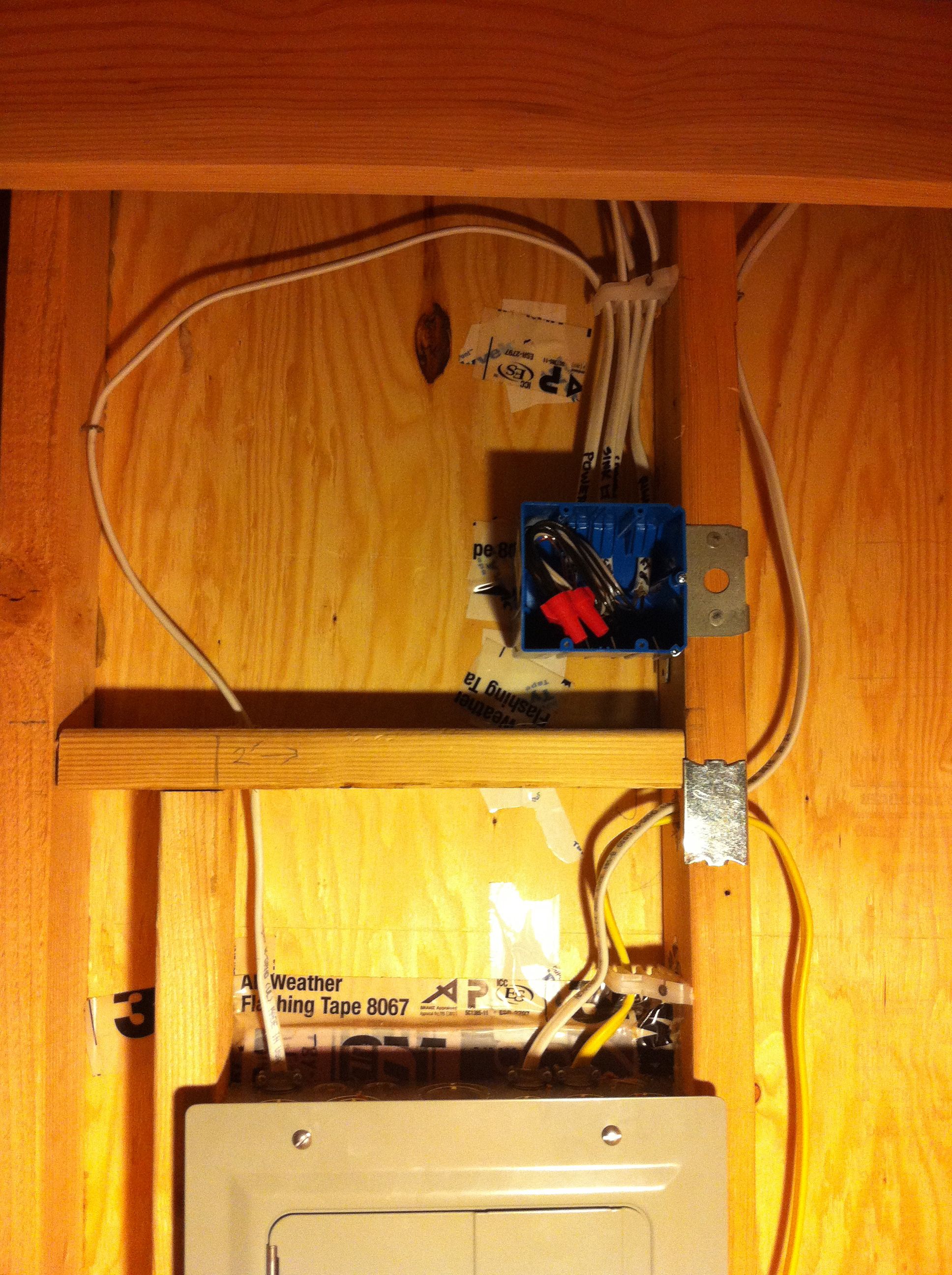
One of my junction boxes.
Exterior device box installation – some differences
As I mentioned, I installed a couple of outlets on the outside of my house. In these cases, thermal breaks and box fill capacity is less of an issue because there is some distance the box has to go through to get through your siding, your rainscreen wall (gap between your siding and your sheathing which you should have), and the sheathing itself. You will inevitably have room for insulation between the back of the box and your interior wall board even if you use a standard 3.5″ deep device box.
You may want to use an old work box so that the wings can hold it in place against the siding. I had to play with this a little to ensure the wings rotated properly to fit through the gap between my siding and sheathing. You also should use a GFCI outlet and a cover with a gasket to keep moisture out. Here is how I installed my exterior outlets (click to see detailed captions):


If you have beveled siding, which presents a slanted surface, you may need to install a backing plate to either make the device you’re installing vertical, or because you need to cut through multiple rows of siding and will have an uneven surface to mount to where the siding overlaps. While my porch light and exterior outlets had a tight fit on a single row of siding, I decided I wanted a backing plate for my power inlet. I will also need to make these for my range hood vent and my gas fireplace vent. The main lesson learned here is you absolutely need a multi-tool with an oscillating blade to cut through the siding cleanly while leaving the sheathing intact (the sheathing only has a small hole drilled through it to run the cable). I knew this but since I didn’t have one, I tried a jigsaw. Despite my best effort, it bucked out when it hit the sheathing and gashed up my siding before I could react. Another thing to consider is installing some flashing at the so that any moisture running down your rainwall won’t rot the top of your backing plate.


As we move into boxes for light fixtures, I wanted to just point out a couple quick tips on switches:
- Switches are different than outlets in that the neutral wires don’t connect to the switch device itself but are wired to each other.
- If you want your switch (or outlet for that matter) to be further out from a stud, you can throw up one or two pieces of 2×4 to create the separation and act as a nailing surface.


As with device boxes for switches and outlets, there are a variety of options for lights and fans. Below are some photo galleries describing how I installed some of the types you might encounter.

A few types of fixture boxes: metal pancake box, nail-in box, hanging box on adjustable sliders, and a fan or saddle box.

A neighborhood walk find…just wanted to see if you are still paying attention!
All Saints’ Day
the moldy pumpkin
grins with a harelip
~ Jane Reichhold
Hanging light box installation
These are typically used in ceilings but I used them on either side of a window to install my sconces since there weren’t studs where I needed them. The nice thing is you can easily position the box left to right along the sliding arms before locking it in place. The hard part is getting it positioned out into the room the right distance to be flush with your wallboard.


Fan or saddle boxes
There were a couple places where I wanted a light right on top of a stud. Later Todd mentioned there were cheaper options, but I used a fan saddle box. These are screwed deeply into the stud and are very heavy duty since they are designed to support the weight, rotation, and vibration of a ceiling fan. Both my lights are swing arms so it was good to know they will be well-supported.


Pancake box installation
Shallow pancake boxes are good for situations where you are mounting a light on a flat surface. My two kitchen task lights are mounted right below the loft, one on a window header that will have paneling around it, and one directly on the end loft joist itself. You could attach the box right onto the surface but it will extend out about a half inch. You could inset it into a wood base, but I wanted a more streamlined, lower profile look. That left me with chiseling out the surface itself. Here is how I did the one on the header:


Having struggled with getting a flat and consistent mounting service in the method above, I came up with a new approach to try the second time, which worked better:


Exterior light box installation
Putting in the box for the porch light was similar to putting in the exterior outlets but I had to figure out what to do about the flange since it wasn’t the right size for my siding depth. All it took was a sawing the flange down with a metal saw. Like with the exterior outlets, this was an old work box.


Tips for rough-in wiring
The hard part of wiring is learning how to navigate through a new world of terms, concepts, materials, safety precautions, and making the final decisions on your wiring plan and circuit diagrams. Actually doing the rough-in wiring is not particularly difficult once you get used to it. After you install your electrical boxes as discussed above, you drill holes in the studs for the cable, run it through from box to box, anchor the cable, install nail plates, and make up the boxes so the wires don’t get in the way of putting up the wall board prior to the final wiring of devices. These are the links I found most helpful:
Resources:
- How to Rough-In Electrical Wiring at TheFamilyHandyman.com
- How-To Electrical at Hometime.com
- Top 10 Electrical Mistakes at TheFamilyHandyman.com
Here are a series of photo galleries illustrating each step as I did the rough-in wiring for Naj Haus. As with the galleries above, click on them to bring up the slideshow. The captions are full of specific tips.
Drilling through studs


Running cable


Anchoring cable


Nail plates


Are you awake?! Not to worry, the end is in sight… (here are some eyeball berries found in our yard for you amusement).
Tips for making up the boxes
Once you have run and anchored your cable, you need to “make up” your boxes. This entails stripping the cable, separating the wires, capping and/or crimping the conductors and ground wires, and tucking them all neatly back into the box so that they are out of the way when the insulation and wall board (whatever you are using to cover your walls) goes up. Later you will come back and wire the devices and fixtures themselves and add cover plates.
I was extremely nervous about stripping the wires and making up the boxes since I didn’t want to screw up. I was also anxious to get my walls up and didn’t feel like stopping and learning yet more skills to properly make up the boxes at that time. Since it was just me putting the walls up, I wasn’t worried about working around the cables sticking out. However, Todd kept asking me if I had made up my boxes and I finally realized that it would be better to do it now so that if I did screw up, I could run a new section of cable easily before the walls were in. So I buckled down and learned what to do, and did it.
Important concepts to understand:
- How to properly strip cable from its sheathing so you don’t nick it.
- It is good to understand exactly how each device or fixture will be wired before making up the box.
- What are pig tails and where do you use them? (Hint: it is better to put in a pig tail and wire it to the device than to wire directly to the device in most cases – this way the current is only redirected through the device when it is in use, otherwise the current can bypass the device easily.)
- Understand wire connectors (wire caps/nuts): the different types, how to choose the right size for a safe connection, and how to properly use them so there is no risk of sparking.
- Understand about using barrel crimps to secure ground wires together (in places where you would otherwise use a screw on wire connector). I gather this is not consistently required by local codes but given the vibrations of a tiny house on wheels, it is definitely highly recommended.
- Figure out how you will know which wires attach to what once they are stripped. For a simple end-of-run device, the color of the wires is sufficient, but you don’t want to lose track in more complicated scenarios. See the photo gallery below.
- Above all, if there is any chance that you will be connecting to your power source before you are completely done installing all your devices and fixtures (perhaps you need a few working lights and outlets to continue building inside), absolutely make sure that you have capped every wire and the grounds are in place so you don’t get shocked accidentally. Always follow proper procedures for disconnecting power sources before working on any box.
Resources
Several of the resources I’ve listed above discuss making up boxes and there are lots of videos out there. Here are some useful links:
- Larry Warner’s video on how to crimp ground wires together (see also some of his other videos)
- Wikipedia: twist on wire connectors
- The Family Handyman: How to make safe wire connections
Here are a couple examples of making up my boxes (click to see tips). I left the wires a little on the long side but will trim them back when I’m wiring in the devices.


You are now finally ready to put up your wall surface and insulate. VERY IMPORTANT TIP: Don’t forget to take lots (and lots) of pictures for later reference before you close it up! As you can see from several of the photos above, I spread out a measuring tape before taking pics and also used a marker to make notes of distances to reference points I’d be able to see when the wall are up. I’ve already gone back to my wiring photos several times to know where wires, studs and other framing is located.
Next phase of wiring:
After the walls are up and whenever makes sense with the rest of your interior work, you will wire in the devices and fixtures. I haven’t done this yet but here are a couple more things to research if you beat me to it:
- If your tiny house is on wheels, spend the extra couple bucks to get professional-grade switches and outlets (available at any electrical or hardware retail store) so that they will hold up better with vibrations of the road.
- Know that there are different ways are to connect wires to a device: creating a wire loop and securing it with terminal screws, backwiring with screws, push-in (stab) backwiring without screws. Either of the first two provide the most long-lasting connection, the last should probably be avoided in a tiny house.
- If you’re using any metal boxes (like a pancake box), research how you should connect the ground wire to the box as well as the device or fixture for safety. Plastic boxes don’t need to be grounded, just the device they hold.
- Electricians seem to love to argue whether it is better to wrap connections in electrical tape or not, so you’ll need to do some research. (Let me know what you find out!)
Concluding thoughts
So though I hadn’t planned on doing my own wiring, I ended up being really glad I was forced into it, not only because of all I learned and the fact that I now know my house’s wiring like the back of my hand, but also because working through the process allowed me to refine my lighting and wiring plan to be much better than it was at the outset. (Plus, I feel a little bad ass!)
Many, many, many thanks to Todd Clay for his patience and guidance and giving me the confidence to do something I would have otherwise avoided like the plague.
For those of you who have made it all the way to the end, you get a sneak peek of my current status (and no, it’s not done; no, I’m not living in it; and no, that’s not the final door!). I’m off to the Build Small, Live Large Summit and then I’m doing a design/build case study presentation at this weekend’s PAD Tiny House Basics Workshop, but hope to catch up on blogging soon.
Peace and be wired!

Naj Haus in its first home behind the barn. If you look closely at the porch, you can see the pumpkin a neighbor kindly gave me.

Sweet Haus! Great blog! Love Auntie So proud of you!!!
Sent from my iPhone
>
Thanks, Cathy! Hope I can see you soon!
So Amazing! I forwarded to a friends daughter who was also wiring a tiny house Deidre Morrison, haven’t met her but her Mom Zoe comes to garden club Wonderful Achievement Kate!
Sent from my iPhone
>
Great, Cath – hope it helps!
Ah, I was at Build Small, Live Large! It would have been nice to meet. Your electrical work looks good.
Thanks, Kjiersten. Sorry we missed each other. Amazing how many people were there!
Hi Kate,
I clicked on the *designing viscerally* link under the *Lighting Design* section which brought me to your site. The link on that article/entry takes me to tinyhomes.com where the post is not found. Am I not looking for it properly? If that post is not on tinyhomes.com – could you email it to me? Thanks!! I have been out of the loop for a bit and currently have a chance to dig deeper into all of the great info you have shared. Would just like to thank you for all of it! 🙂
Cheers, Julie
Hi Julie – thanks for bringing my attention to the broken link! I see that TinyHomes.com has changed radically from what it was when I was blogging for it and they’ve deleted all of the blog posts. Unfortunately I didn’t keep a copy of that one – my bad, especially since it was near and dear to my heart. I’ve just written to them to see if they still have it. If so, I will post it on my site and let you know, but I fear it may gone altogether. I can try to recreate it at some point but not sure when that will be since I’m behind on posts as it is. Fingers crossed it will appear!
This post providing more information than I have found anywhere (including paid for info)
Thanks for posting
Thanks, Kellie – glad it was helpful!
Kate,
This is SO helpful! I am starting the process of designing my electrical system and this is a great resource. Thank you!
Glad it helps – thanks! One of these days I hope to get a follow-up post on putting in the fixtures and receptacles, but it might be awhile!